What is Fusion 360?
Fusion 360 is Autodesk's cloud-based 3D CAD (Computer aided Design – known as 3D modelling), CAM (Computer aided Manufacture) platform that combines design, engineering, and manufacturing in a single tool. This means people can create renders, animations, assemblies, stress testing, technical drawings and more all in one software.
It's particularly popular for product design, mechanical engineering, and 3D printing and can be used for simple to more complex projects.
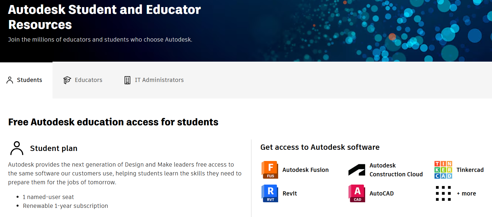
How can I access Fusion 360?
If you are a current student or staff member at an educational institution, you are able to apply for a free educational license.
Visit https://www.autodesk.com/education/home for more information and to download.
Fusion 360 is also available on uCreate Makerspace computers.
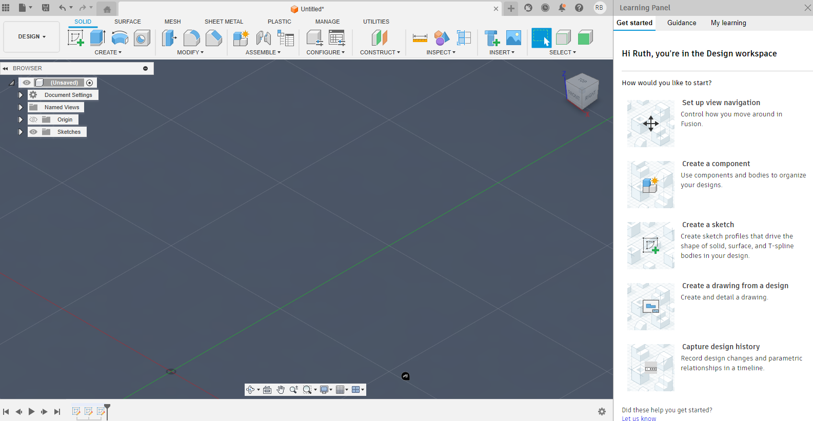
Interface overview.
The Fusion 360 interface is broken up into 6 different sections. The different tools within these sections are detailed below.
Top Menu Bar
- File operations (New, Open, Save)
- Account and preferences access
- Includes all of your opened projects in tabs
- Help and learning resources
Toolbar
- Contains tools specific to your current workspace (here you can see the SOLID’s workplace is selected in the DESIGN workplace; showcasing the design tools you can use)
- Changes to tools will be different based on selected workspace (Design, Render, Animation etc.)
Browser Panel (Left Side – Design Tree)
- Shows your design history timeline
- Displays components, bodies, and sketches and the tools selected which can then be edited or hidden.
- Organises your project structure
- The arrow allows you to expand the tree to access all the sketches for example – double clicking on them will help you edit them too.
- Edit document settings if needed.
Canvas (Centre of the page)
- Main 3D viewport where you create and view models
- Displays what you are making
- Uses perspective (may look distorted when used – it is similar to how we view the world) or orthographic projection (more useful when editing and looking at the product when not rendering)
- Supports real-time rendering through the Render Menu – for a more realistic view.
Timeline
- Shows chronological history of operations (which can be time-lapsed)
- Allows editing previous steps or moving them around – be careful as some edits or movements may make others unable to function, creating an error.
- Enables parametric design changes so you do not need to work in a linear way – always have space to go back and edit what you have done within the timeline as it is not permanent – therefore make mistakes, don’t worry and experiment! You can always change things even after a looong time!
Workspace Selector
Located in the top-left corner, this dropdown lets you switch between:
- Design: Primary modelling workspace
- Render: Photo-realistic visualization
- Animation: Motion studies and presentations
- Simulation: Stress analysis and testing
- Manufacture: CAM and toolpath generation
- Drawing: Technical drawings and documentation

Basic navigation.

Mouse Controls
Orbit (Move and Rotate View)
Move around: Middle mouse button + drag
Free Rotation: Shift + middle mouse button + drag
Zoom
Mouse wheel scroll
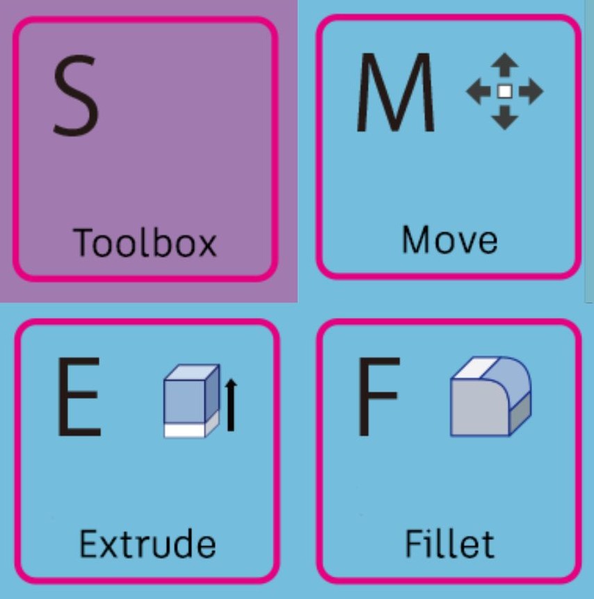
Keyboard Shortcuts
S: In Sketch mode - shortcuts
E: Extrude command
F: Fillet command
M: Move/Copy command
Ctrl + Z: Undo
Ctrl + Y: Redo
Delete: Remove selected objects
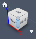
ViewCube (Top-Right Corner)
Click faces for standard orthographic views
Click edges for isometric views
Drag to rotate freely
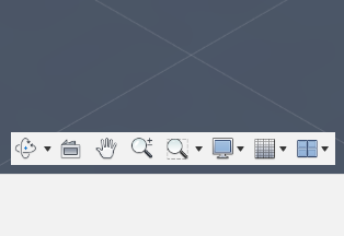
Navigation Bar (Bottom)
Zoom tools
View orientation options
Display settings
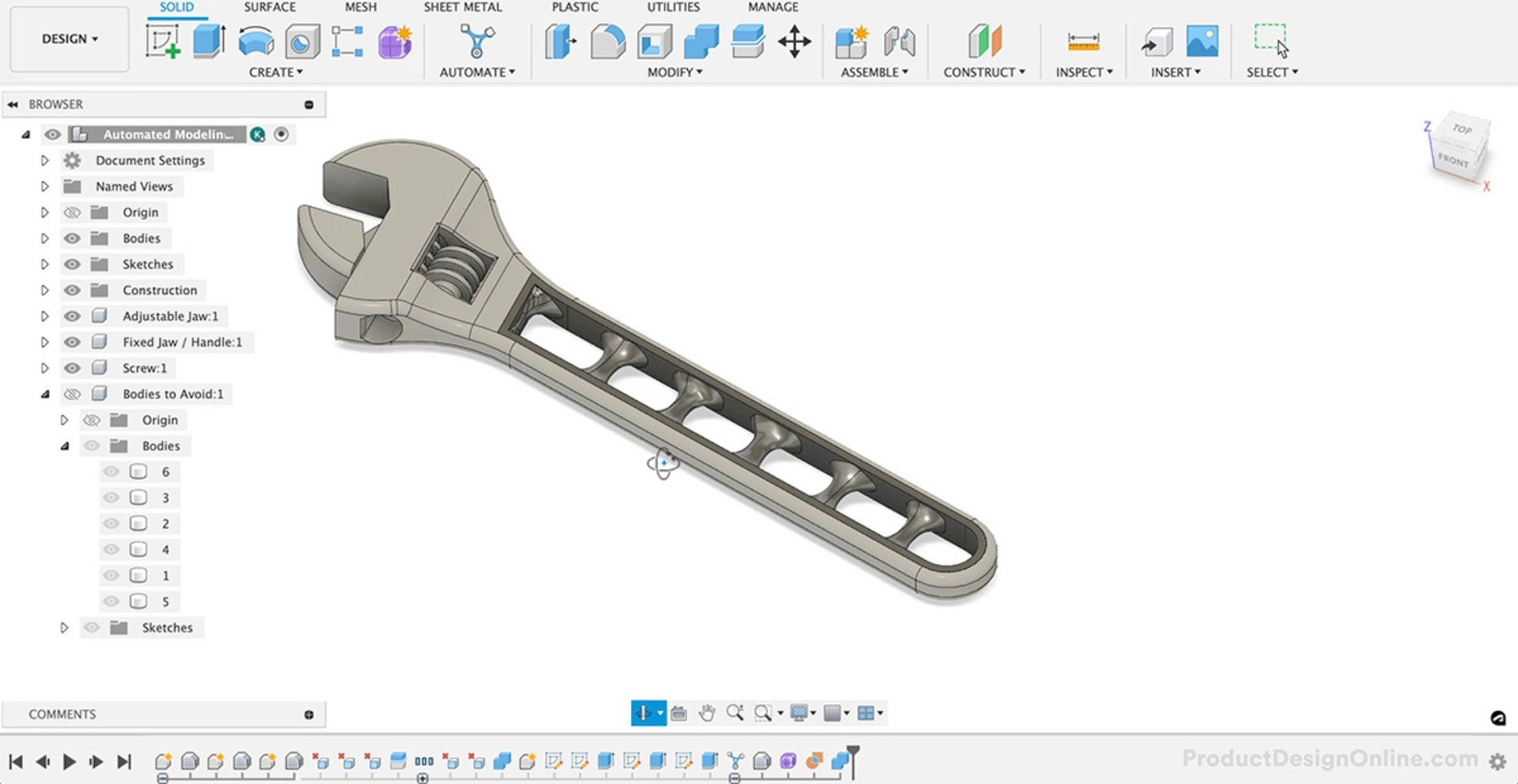
The design workspace.
The 'Design' workspace is the primary workspace for 3D modelling.
The workspace contains multiple panels, all with different tools within. Some of the key tools in each panel are listed below.
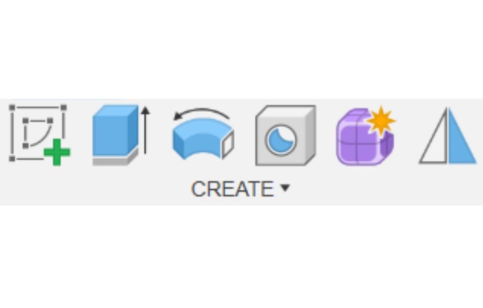
Create Panel
Sketch: 2D drawing tools
Extrude: Convert 2D sketches to 3D
Revolve: Rotate sketches around an axis
Sweep: Follow a path with a profile
Loft: Blend between multiple profiles
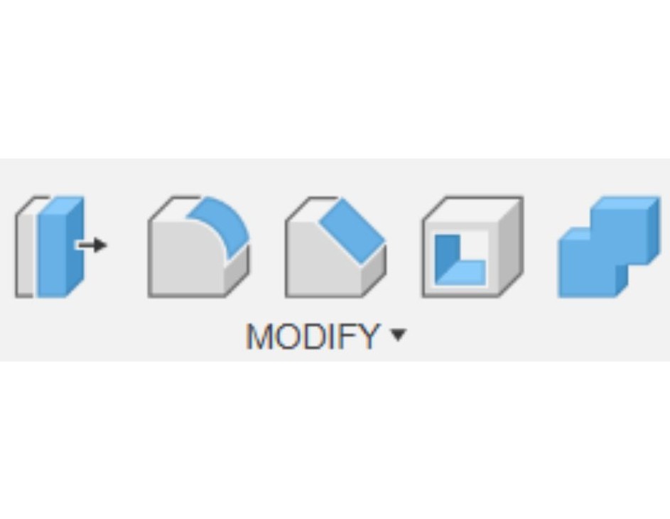
Modify Panel
Fillet: Round edges and corners
Chamfer: Create angled cuts
Shell: Hollow out solid bodies
Mirror: Create symmetric features
Pattern: Duplicate features in arrays
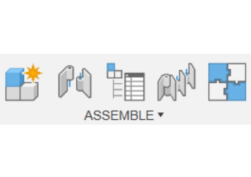
Assemble Panel
New component: Create empty component in the design
Insert component: Add existing component from another design
Joint: Add a joint to the assembly
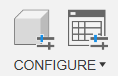
Configure Panel
Configure: Create and manage multiple design variations in the file
Display configuration table: Open the display configuration table
Construct Panel
Plane: Create reference planes (add more than the x, y, z that is initially available)
Axis: Define rotation axes
Point: Place reference points so it can help when sketching – especially when finding it difficult to click on areas or find centre points for example
Inspect Panel
Measure: Check distances and angles
Section Analysis: Cut through models
Curvature: Analyse surface quality
Insert Panel
Insert fastener: Add bolts, screws, nuts and washers to the design
Insert mesh: Add an existing mesh to the design

Select Panel
Select: Selects any edge, face, body or component
Select edge priority: Selects edges only
Select face priority: Selects faces only
Select body priority: Selects bodies only
Select component priority: Selects components only
Sketching fundamentals.
Starting a Sketch
- Click "Create Sketch" in the toolbar
- Select a plane (XY, XZ, YZ) or existing face if you have modelled something and wants to draw on it
- The view automatically orients to the sketch plane so you will see everything in 2D
- Begin drawing with sketch tools – Click Finish at the top right corner when done with sketching.
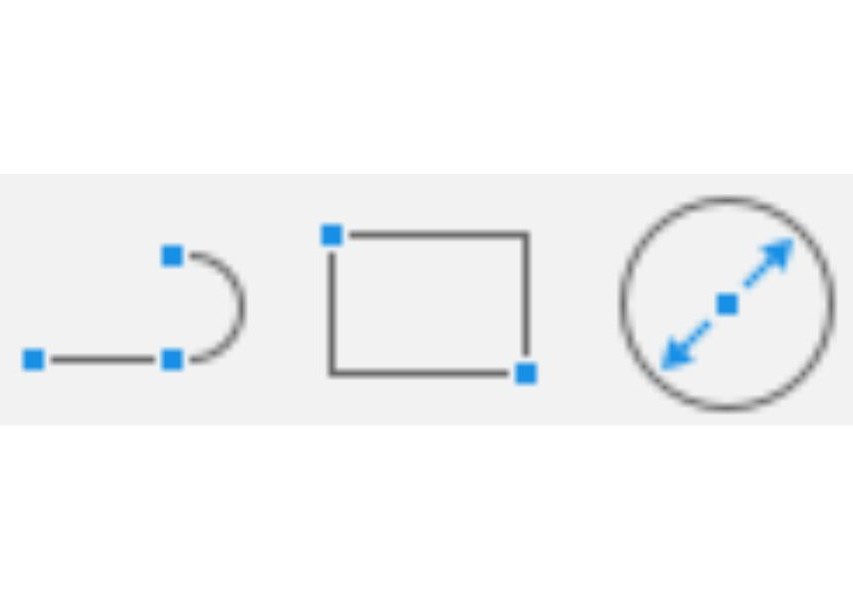
Essential Sketch Tools
Line Tool: Click to place start and end points. Press Escape or right-click to finish.
Rectangle Tool: Click first corner. Drag to opposite corner. Click to confirm.
Circle Tool: Click centre point. Drag to set radius. Click to confirm.
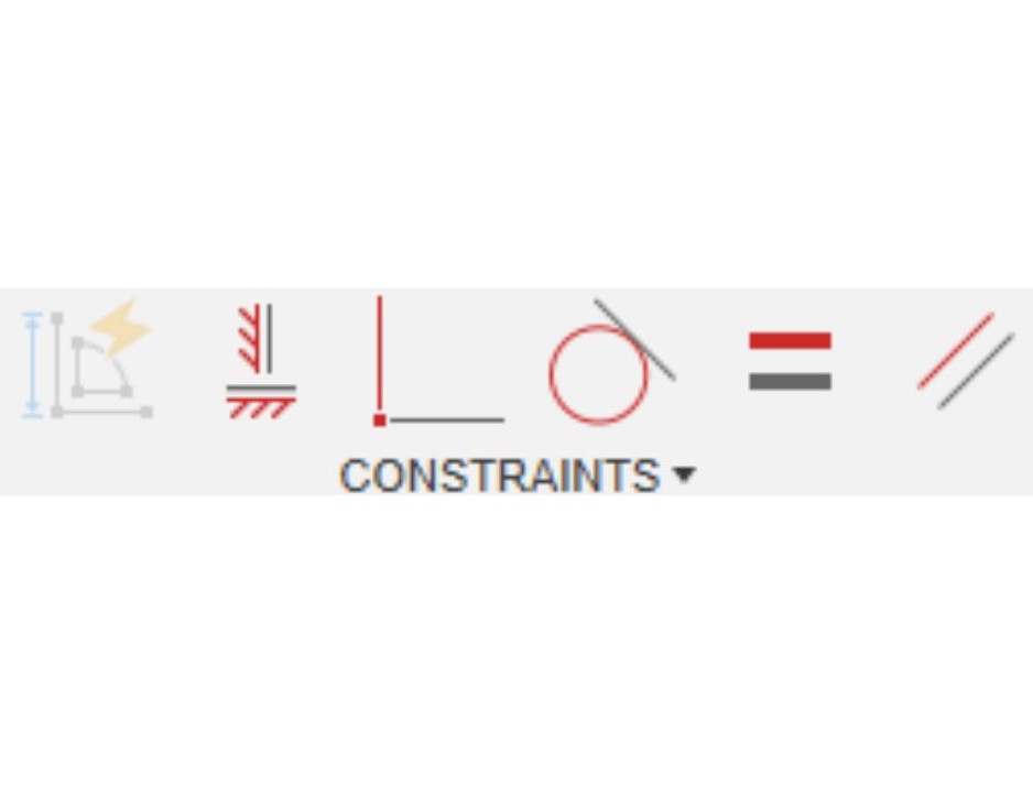
Sketch Constraints
Constraints define relationships between sketch elements.
Coincident: Points touch
Horizontal/Vertical: Lines align with axes
Parallel/Perpendicular: Line relationships
Equal: Same length or radius
Symmetric: Mirror relationships
Sketch Best Practices
Fully Constrain Sketches: Eliminate blue geometry (under-constrained whilst black means constrained and will not be able to be moved)
Use Construction Lines: Create reference geometry
Start with Basic Shapes: Build complexity gradually
Name Important Sketches: Organize your timeline
Keep Sketches Simple: One feature per sketch typically
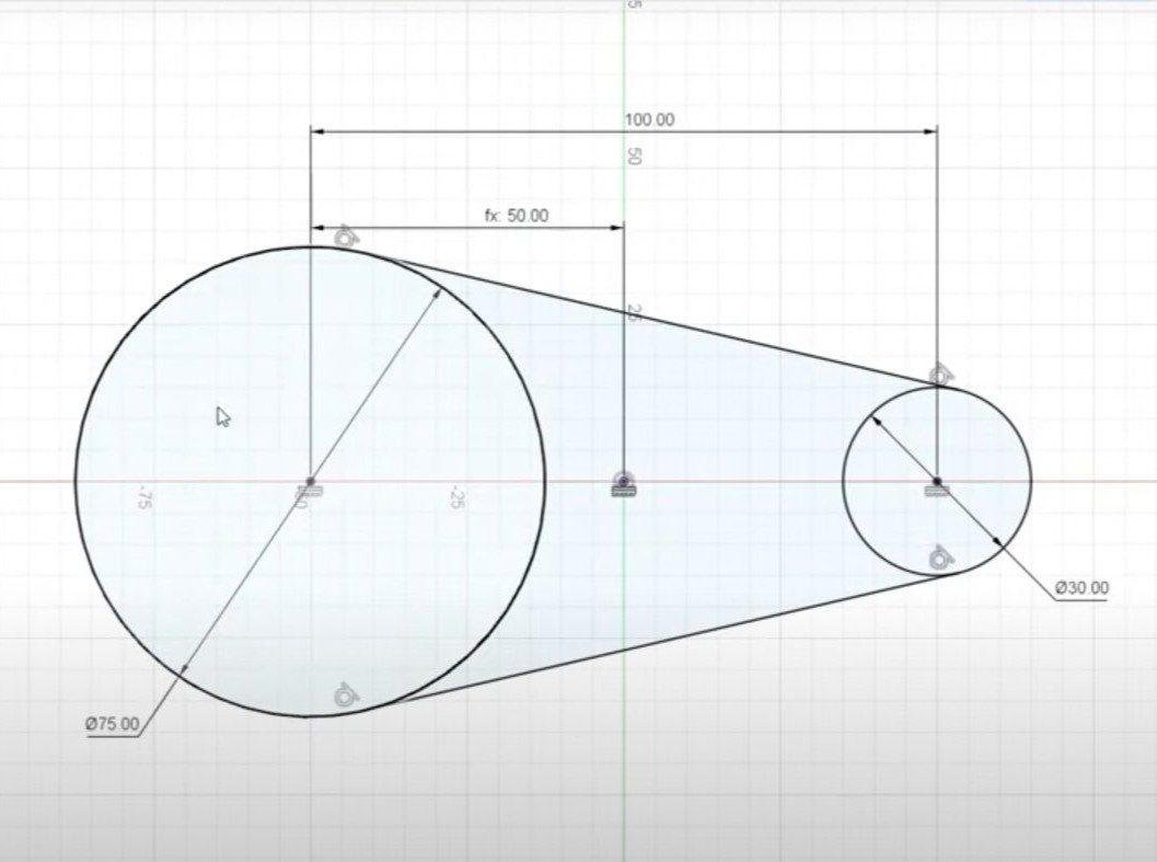
Sketching and creating basic parts in Fusion 360.
This video showcases various tools and how to get started with modelling in Fusion 360.
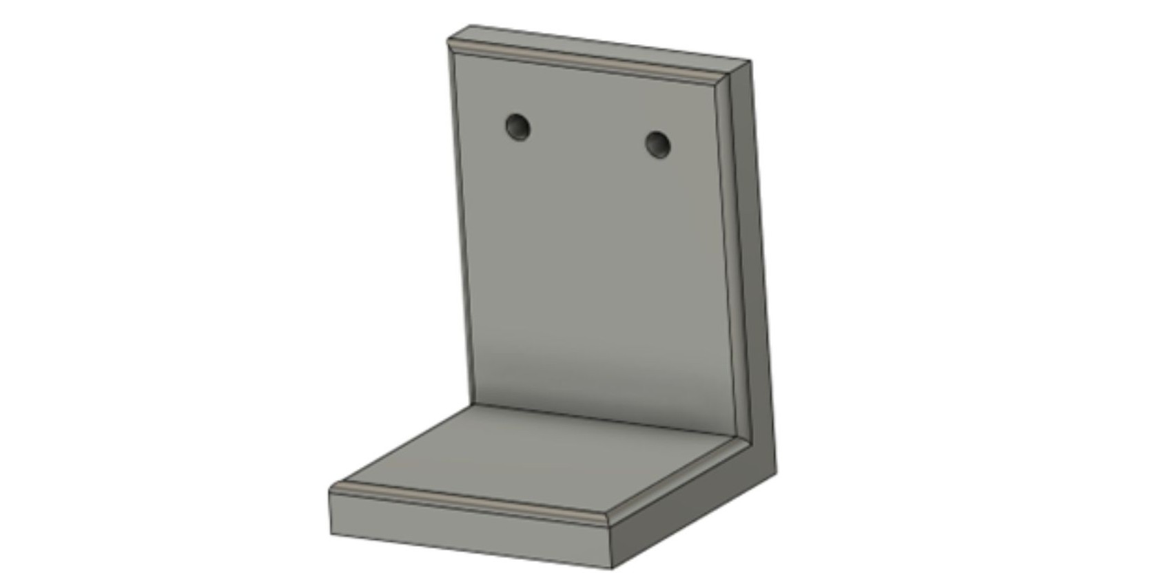
Design a simple bracket project.
If you would like to practice your Fusion 360 skills. Try to create a mounting bracket using the step-by-step instructions.
The instructions can be downloaded here.
Assembly fundamentals.
In Fusion 360 you are able to piece together multiple 'components' to make larger assemblies.
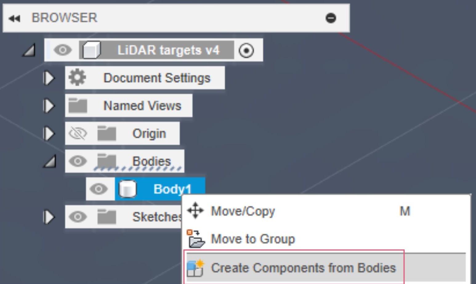
Creating components from existing bodies
- Right-click body in browser
- Select "Create Component from Bodies"
- Name the component appropriately

Creating new components
- Right-click root component
- Select "New Component"
- Activate component for editing

Creating Joints
Joints define how components move relative to each other.
Types: rigid, revolute, slider, cylindrical, pin-slot, planar.
- Select Assemble > Joint
- Choose first component geometry
- Choose second component geometry
- Select joint type
- Adjust position and orientation
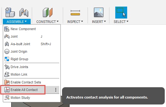
Contact Sets
Define how components interact.
- Enable collision detection
- Set up motion limits
- Configure advanced contact properties
Rendering fundamentals.
Switch to the Render workspace for producing photo-realistic images of your 3D model.
Setup Scene
- Position camera using navigation controls
- Add environment from gallery
- Adjust lighting intensity and direction
Apply Materials
Using the 'Appearance' function does not change the physical properties of your model, for this use 'Physical Materials'.
- Drag materials from library onto objects
- Adjust material properties
- Create custom materials as needed
Render Settings
- Set image resolution
- Choose quality level
- Configure rendering effects
- Start local or cloud render
Tips and best practices.
Design Methodology
Start with overall form and proportions.
Add details progressively.
Consider manufacturing constraints early.
File Organization
Use descriptive names for all features.
Include version numbers for iterations.
Organize related files in projects.
Group related components.
Use folders for complex assemblies.
Performance Optimization
Use appropriate detail levels.
Suppress unnecessary features when possible.
Adjust visual quality for performance.
Use simplified representations for large assemblies.
Cloud Integration
Automatic file syncing – have access to your files on any device.
Version history tracking.
Share designs with team members.
Comment and markup tools.
Where can I find out more about Fusion 360?
Fusion 360 has built-in help tools in the software. This means that when hovering your mouse over a button, a description of what that icon does will appear.
There is also a 'Learning Panel' within Fusion 360 with further information on all the tools and online forums.
There is also extensive online documentation.
https://help.autodesk.com/view/fusion360/ENU/
We also have a Fusion 360 common problems knowledge base page with more troubleshooting tips.
In addition, there are Fusion 360 courses available on LinkedIn Learning (accessible with University email) and multiple tutorials on YouTube.